How to Connect Two T1000s LED Controllers
In the user manuals for pixel LED controllers, the term “cascading” may have appeared. In our view, this capability of the pixel LED controller should be called “networking“. “Cascading” is how the system is referred to. We connect two T1000s LED controllers to get synchronized playback from each controller in the network. The maximum number of networked pixel LED controllers varies depending on the controller type (read the controller user manual). The original pixel LED controller for the network is called the “Master” controller. When additional controllers are networked, their button functionality will not operate. The master controller will only operate with button functionality.
Table of Contents
Why connect two T1000s LED controllers?
Let's look at an example. Let's say I have a single-port pixel LED controller called a T1000. With its single port, this controller can only control up to 2048 pixel LEDs. Say you need to program more than 2048 pixel LEDs. You may use a multi-port pixel LED controller without networking (e.g., T-4000, T-8000). Compared to the T1000s LED controllers, these multi-port pixel LED controllers are ten times more expensive. Networking pixel LED controllers is helpful in this situation. Without needing to buy an expensive pixel LED controller like the T-8000, you can network these in-pixel LED controllers to create your pixel LED system.
Another advantage is that if a controller in the network is damaged, you may simply replace the damaged pixel LED controller rather than the entire network. simple and inexpensive. If you use a multi-port pixel LED controller, which is fairly costly, you must replace the entire controller unit.
How to connect two T1000s LED controllers?
Let us now examine how to connect two T1000s LED controllers. I’ll be using two T1000s LED controllers in this lesson. We'll use custom animation to show you how this system works as a whole.
As discussed in our guide on the T1000s LED controller, to each pixel-led controller in the network, we must connect the power and the pixel LED strings or strips.
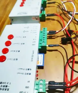
Power Supply Wiring: The power supply must be connected to both the controllers and the pixel LED strips or strings. Multiple power supplies are available. However, a common ground must be used between the power supplies. The GND of the pixel LED strip or string does not need to be connected to the controller if you are using a common power supply controller for the pixel LEDs and pixel LED controllers.
Pixel LED wiring: Through the data and clock terminals, the pixel LEDs must be linked to the pixel LED controller (depending on the type of pixel LED string or strip). The wiring pattern and pixel LED layout should be followed while installing the device.
Networking Controllers
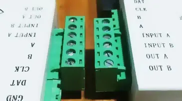
To network the pixel LED controllers together, there are four terminals. Inputs A and B, as well as Outputs A and B These are the four ports we need to connect pixel LED controllers. The two outputs of the previous controller should connect to the inputs of the next pixel LED controller. The A terminal should connect to the A terminals, and the B terminals should connect to the B terminals.
Although the user manual says that you need to connect both “A” and “B” lines, we found out that that is not the case. The communication between the controllers happens through the “B” line. So, you may not have to connect the two lines. Only the “B” line connection will do the job. Use color-coded wires for networking. It helps you not to mix up the wiring.

Pixel LED Effects Download Pack: 7000 Effects
- Files: 7000+
- Size: 25 GB
- Formats: SWF, TOL, AVI, MP4, and GIF
T1000s Wiring Diagram 2
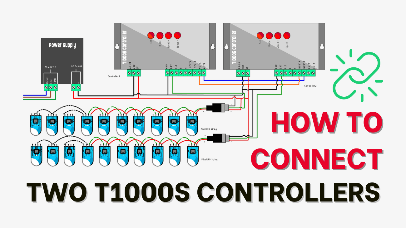
In this example, we are networking T1000s pixel LEDs together. Each controller is connected to a single WS2811 Pixel LED string, which contains 50 Pixel LEDs. Here is the wiring diagram for the system.
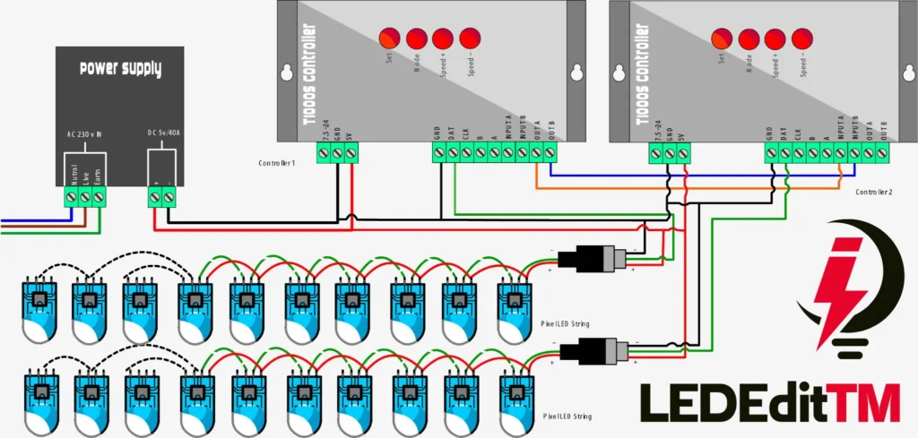
As you can see in the wiring diagram, we are using a common power supply for both pixel LEDs and pixel LED controllers. The pixel LED strings only connect to the controller through the data coming out of the controller. The first pixel LED controller in the network is called the master. The master pixel LED controllers' OUT A connects to the next pixel LED controller's INPUT A, and the master pixel LED controllers' OUT B connects to the INPUT A of the next pixel LED controller. The same connection method should be used for the next pixel LED controller in the network.
Programming Two T1000s LED Controllers
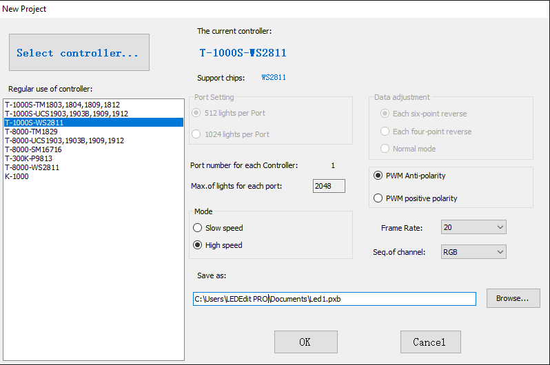
Create a new project. From the list, choose your controller and pixel LED. In the end, press the “OK” button.
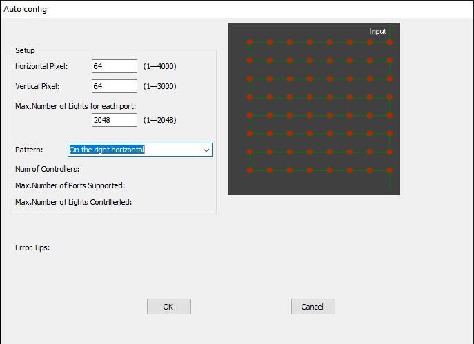
Create the layout as you wish. Use the manual layout editor or automatic layout creator. If you are using the manual layout creator to create the layout, Create a port for every pixel LED controller in the network, and connect the group of pixel LEDs in the layout to the particular port. Here are some of the related articles on creating pixel LED layouts.
For this example, we will create a 64×64 panel layout using the auto layout creator.
- Click on “Project Configuration“. Then, select “Auto Layout” from the drop-down menu.
- In the Auto Layout Creator window Type the number of pixel LEDs along the horizontal and vertical axes of your pixel LED layout.
- Type the limitation of the pixel LED controller in the “Max Number of Pixels for Each Port” input field.
- Select the connection pattern from the “Pattern” drop-down list.
- Once all is done, click “OK“.
In this example, we have a 64×64 Pixel LED, which results in 4096 Pixel LEDs. Since then, the T-1000s can only control up to 2048 pixel LEDs. The automatic layout creator will create two separate ports. Each port represents a controller port (in this case, two ports mean two controllers). which means, in this case, a new controller in the network (since this controller has only one port). There is no connection between the two groups of pixel LED strings except for the power. Each pixel LED string groups data and clock lines, which will connect to the specific port of the controller. The above image shows the final layout of the pixel LED system.
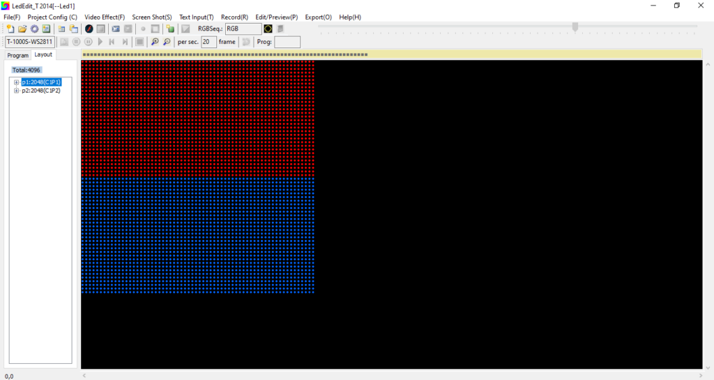
Even though this system has two separate sections, it works as a single layout. The result is the same as if you used a multi-port pixel LED controller. It's no different, except for the wiring and programming.
Recording | Programming
It's the same way you program your other pixel LED program. There is no difference between the two.
Open a video, SWF, or TOL animation, or use a default animation by clicking on “Video Effect” and selecting an option.
Once the animation or the video is opened, click on the “record” button (“Red Dot“). Click the “stop” button (a green rectangle with a white fill) to end the recording.
Once recorded, edit the recording by clicking on the “Edit recorded” button. Please see the article below to learn how to edit the recorded animation or video.
Exporting
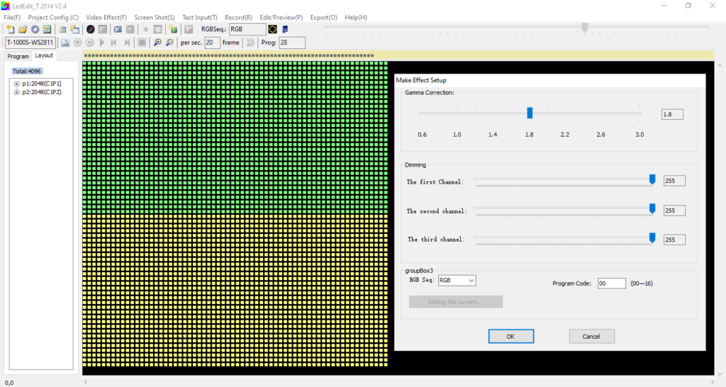
Once your recording and programming are done, you can export your pixel LED effect. Click on “Export” and select “Export LED Effect (.led)“.
In the export settings window, change the settings as you wish.
After changing the settings, click “Export“.
Select a location to save the LED effect files. Click on “OK“.
Copying the Files
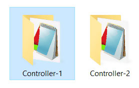
If you go inside the “LED” folder that the LEDEdit software creates, there will be folders for each controller. With the controller, number Go inside these folders and copy the effect file into the controller folder. Then, paste it into the root directory of the SD card. The SD card should be numbered. For example, the SD card for Controller 1 should be labeled “1“, and so on. The effect files should not be mixed.
Insert the SD cards into the pixel LED controllers that they belong to. E.g., the SD card that contains the program for the controller one should go inside the pixel LED controller one. After inserting all of the SD cards, Turn the power supplies on. The pixel LED system will be demonstrated as a single unit. You can increase the number of pixel LEDs in the system by adding more pixel LED controllers to it.
Troubleshooting
If you like LED software, you may also like:
We hope you find this tutorial useful. Thanks for reading.