We’ve reached 156K followers! ✨🎉
Thanks to your amazing support and love, our page has grown to this milestone 🙌💙
To celebrate, we’re giving you $10 OFF 🎁💵
Coupon: 156kfollowers

Thanks to your amazing support and love, our page has grown to this milestone 🙌💙
To celebrate, we’re giving you $10 OFF 🎁💵
Coupon: 156kfollowers
In this lesson, let's talk about the T-300K LED controller online control. When it comes to live events, online control is critical. You must have real-time control of the display so you can change animations or videos according to the situation. This gives you the ability to display important live updates and share screens.
T-300K Pixel LED Drivers can drive up to 8192 LEDs. You can connect a maximum of 1024 LEDs per port. There are 8 ports. The offline features are very identical to those of the T-8000 LED Controller. It has controller networking capability (cascading), similar to the T-8000 Pixel LED controller. It supports both 3 wire Pixel LED strings or strips (VC, Data, and GND) and 4 wire LED strings or strips (VC, Data, Clock, and GND). Also supports RS485-based Pixel LED strips or strings. Most importantly, it supports both offline and online operations.
When it comes to Pixel LED programming, The higher the frame rate, the smoother the transition. A low frame rate means a rough transition, and you will start to see the frame-by-frame change.
If you are using less than 512 LEDs or pixels per port, you can use 30 fps (frames per second) as the frame rate for the animation or video. If you are using more than 512 LEDs or pixels per port, the frame rate will automatically reduce.
The software plays the most important part when it comes to Pixel LED programming. LEDEdit is the most advanced and most developed Pixel LED programming software available today. To program the T-300K LED Controller, you need LEDEdit 2014 or later software versions. Please download and install the latest LEDEdit software version from the below link before continuing.

When you are selecting the controller from the list, please follow this method.
Controller Name in the list = Controller Name + Drive Chip Name
If your controller's name is T-300K and your drive chip's name is WS2811, you should select T-300K-WS2811 from the list.
TM1803, TM1804, TM1809, TM1812, TM1829, TM1913, TM1914, UCS1903, UCS1903B, UCS1909B, UCS1912, UCS2903, UCS2909, UCS2912, UCS3903, UCS6909, UCS6912, UCS7009, UCS5903, UCS8903, UCS512, US2811, WS2821, P9813, P9823, LPD1886, GW6202, GW6201, GW6202B, GW6204, GW6203, GW623X, TA9909, MBI6021, INK1003, LX10003, LX2003, LX2006, TLS3100, DMX, SM16711, SM16726, SM16716, LPD6803, LPD8806, LPD1882, LPD6812, TM1903, TM1904, TM1909, TM1912, DMX, Monochrome, WS2801, WS2803, D7710, QC1109, TLS3001, TLS3008, APA102, MY9221, BS0815, BS0825, BS0901, HL32, HL1809, HL2803, RGB, Monochrome, XB001, XB002.
Note: Not every T-300K LED Controller supports the above-listed driver chips. Please consider asking your seller about supported LED drive chip names.
Online operation is archived by connecting the T-300K LED Controller with the PC or laptop via the VIA network port (RJ45) using a Cat5, Cat5e, or Cat6 cable. The software sends real-time data via a network port to the controller. You can also network (cascade) the controllers, allowing you to control more than 8192 LEDs. Online mode's main goal is to use the PC or laptop as a video console. Since video consoles are very expensive, this is the best and cheapest way around it.
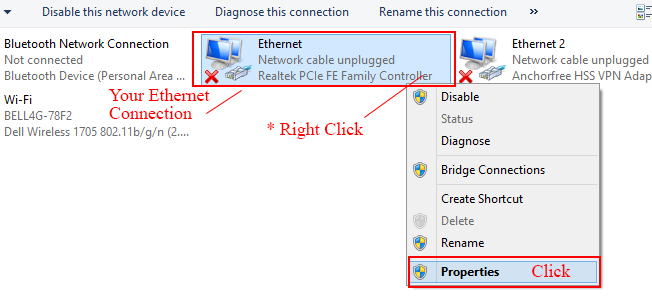
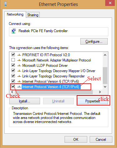
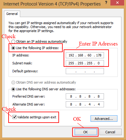
For the controller to communicate with the software, the IP of the PC must be set to 192.168.60.178. Let's see how to do it. This is how to do it in Windows 8, but the same steps apply to other Windows versions. Please make sure your Ethernet adapter drivers are installed correctly.


There are four different methods when it comes to wiring the controller.

In this case, a single T-300K LED Controller is connected to the PC via a VIA Ethernet port. The PC Ethernet port is connected to the “NET 1” port of the controller using a Cat5e cable. In this case, 3 wire (VCC, DATA, and GND) LED strips are used with a common power supply. You can use more than one power supply. Please refer to my “How to Select Power Supply for Your Pixel LED Project” article (HERE) for more details. The connection table is shown below.


In this case, two or more T-300K LED Controllers are networked. The first T-300K LED Controller in the network is connected to a PC via a VIA Ethernet port. The PC Ethernet port is connected to the “NET 1” port of the first controller using a Cat5e cable. The “NET 4” port of the previous controller is connected to the “Net 1” port of the next controller. In this case, three-wire (VCC, DATA, and GND) LED strips are used with a common power supply. Here is the connection table.


In this method, a single T-300K LED Controller is connected to a PC via a VIA Ethernet port. The PC Ethernet port is connected to the “NET 1” port of the controller using a Cat5e cable. In this case, 4 wire (VCC, DATA, CLOCK, and GND) LED strips are used with a common power supply.


In this case, two or more T-300K LED Controllers are networked. The first T-300K LED Controller in the network is connected to a PC via a VIA Ethernet port. The PC Ethernet port is connected to the “NET 1” port of the first controller using a Cat5e cable. The “NET 4” port of the previous controller is connected to the “Net 1” port of the next controller. In this case, 4 wire (VCC, DATA, CLOCK, and GND) LED strips are used with a common power supply. Here is the connection table.

If you are planning to use more than 8192 LEDs or pixels for your display, you have to use two or more controllers networked together. The PC or laptop should have an Ethernet or LAN port, and the drivers need to be installed. The NET 4 port of the first controller is connected to the PC Ethernet port via a Cat5e cable. NET One port of one controller is connected to the NET 4 of the next controller. This way, you can network up to 33 controllers. Since we have more than one controller, each controller in the network needs to be identified. For this reason, there are 8 DIP switches on the right side of the controller. The first controller in the network (the controller that is connected to the PC) is “ID:001.” “ID:002” is the second controller, and “ID:003” is the third. Likewise, you have to set the controller IDs for every controller in the network.
These DIP switches change value in binary format. You have 8 bits, which is equal to a byte. You can set decimal values between 0 and 255 using these DIP switches. If a DIP switch is turned upward, it means the bit at that position is 1. If a DIP switch is turned downward, it means the bit at that position is 0 (zero).
Note: The binary values increase from right to left, but the DIP switches are positioned in the opposite direction. To avoid confusion, please consider the number below each DIP switch, which is the bit number in binary format. Here are some binary values, DIP switch positions, and corresponding decimal values. If you don't know about binary to a decimal convention, please google binary to decimal convention for more information.

Pixel LED Effects Download Pack: 7000 Effects for LEDEdit
https://lededittm.com/pixel-led-effects-download-pack-7000-effects-for-lededit